

 Home>News>Industry News>Acceptance criteria for FPC patch processing products
TRUSUN provides one-stop customized PCB solutions for global customers
Date:2026-09-04Edit:TRUSUNBrowse:6
The quality of flexible printed circuit board (FPC) patch processing directly affects the lifespan and performance of electronic products. To ensure product reliability, strict acceptance standards must be followed. This article will systematically introduce the acceptance requirements for FPC patch processing products from the aspects of appearance, electrical performance, soldering quality, mechanical reliability, and packaging labeling.
Appearance inspection standard
The appearance is a direct reflection of the quality of FPC, and it needs to be inspected under sufficient lighting conditions (such as 30W fluorescent light) and an observation distance of 30±5cm
Screen printing and polarity: The polarity markings (such as white screen printing) on the components must be consistent with the screen printing direction on the PCB board. Reject if the directions are inconsistent
Solder joint quality
Tin quantity control: Solder can extend to the top of the solder pad or end cap metallization, but it must not touch the component body. Contact with the component body is considered non-conforming
Cold soldering and empty soldering: The solder joint should be moist and full, with a smooth surface. Incomplete reflow, black and gray tin color, presence of unmelted tin powder, or lifted component leads are all indications of cold soldering and empty soldering, which are defects
Component placement: Components must be neatly and precisely placed, without any offset or skew. There must be no missing, incorrect, or reversed placement. Polarized components must be installed in the correct orientation
Surface defects: The FPC surface should be smooth, free of scratches, dents, contamination, oxidation, and protruding deformations. The board bottom wiring, copper foil, through
Electrical performance inspection
Electrical performance is the core of FPC functionality, and all circuits must meet the electrical characteristics required by the design.
Conduction and insulation: Use instruments such as multimeters to conduct conduction tests to ensure that the circuit path is free from short circuits and open circuits. The insulation resistance must meet the requirements (such as testing for 1 minute at DC 500V, with insulation resistance ≥500MΩ), and there must be no leakage
Signal transmission: A signal transmission test is required to verify that the signal is free from attenuation, interference, and distortion
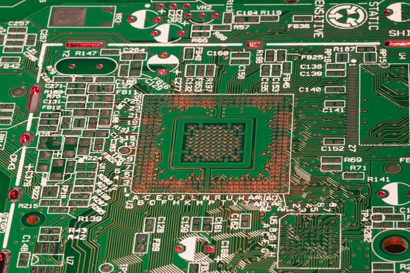
Special inspection of welding quality
The quality of welding is crucial to the reliability of the connection, and the following details require special attention:
Solder pads and solder joints: The solder pads should be intact, without oxidation or missing parts. The solder joints should be secure, without cold solder joint, solder skips, or solder bridges. The connection between the solder pads and the circuits should be good, without open circuits or short circuits
Polarity components and inversion: Inversion of polarity components is a fatal defect. Each board is allowed to have one 0402 package chip component inverted, but it must be ensured that no electrical materials are exposed. Rejection will be applied if there are two or more
Mechanical performance and reliability verification
The flexible nature of FPC requires it to pass rigorous mechanical and environmental testing.
Bending performance: When bent at a specified bending radius, there must be no fracture or cracking. Repeated bending life testing (such as bending back and forth 5 times) is required to ensure that the circuit is free of cracks and the electrical performance is stable
Environmental adaptability: It is necessary to conduct high and low temperature, damp heat tests (such as high temperature shock, solderability test in tin furnace) to observe whether its performance is stable. Its reliability under vibration and shock should also be evaluated
Dimensional accuracy: Measurements are taken using tools such as calipers and microscopes. Key dimensions such as length, width, thickness, hole diameter, and hole spacing must fall within the design tolerance range (commonly ±0.2mm for overall shape tolerance, and ±0.05mm or tighter for precision features)
Packaging and labeling verification
Packaging and labeling are the guarantees for product traceability and reliable transportation.
Packaging: The outer packaging should be intact, without any damage or contamination. The inner packaging must be able to prevent FPC from being damaged during transportation
Marking: The marking on the product (such as model number, batch number, production date) must be clear, accurate, and consistent with the delivery note and BOM list
Acceptance process and sampling standards
When conducting acceptance inspection, it is necessary to follow clear procedures and sampling rules:
Sampling plan: Normally, normal single sampling is conducted in accordance with ISO 2859-1 (GB/T 2828) Level II. The AQL values are typically set as follows: critical defects (CR) = 0, major defects (MA) = 0.65, and minor defects (MI) = 1.5
Defect Level:
Critical defect (CR): Causes the product to malfunction or presents safety hazards, such as short circuit, open circuit, or reversed polarity.
Critical defect (CR): Causes the product to malfunction or presents safety hazards, such as short circuit, open circuit, or reversed polarity.
Minor Imperfection (MI): Cosmetic flaws that do not affect functionality, such as minor scratches, unclear characters
Tools and Environment: Commonly used tools include microscopes, calipers, multimeters, insulation resistance testers, etc. The inspection environment typically has a temperature of 23±3℃ and a humidity range of 40-70%
Conclusion
The acceptance of FPC (Flexible Printed Circuit) patch processing products is a multi-dimensional and systematic process, involving various aspects such as appearance, electrical properties, soldering, mechanical reliability, and packaging labeling. Strictly adhering to the aforementioned standards is a crucial step in ensuring the reliable quality of FPC products and meeting the demands of high-density, miniaturization, and high reliability in electronic products.
After the pre-treatment process of FPC electroplating, the coppe...
The design of a multi-layer PCB is different from that of a sing...
The quality of flexible printed circuit board (FPC) patch proces...
In the production and application of PCB circuit boards, surface...

As an indispensable key component in modern electronic devices, ...
 Contact TRUSUN